Schematic diagram of a control valve Control valve positioner circuit diagram Valves timing mechanism engineeringlearn schematic diagram of valves
[DIAGRAM] 3 Way Valve Block Diagram - MYDIAGRAM.ONLINE
Valve globe plug diagram valves gate ball water control flow line main disc butterfly work do type svg vs plugs File:globe valve diagram-en.svg [diagram] specific heat diagram
[diagram] sloan valve diagram
[diagram] 3 way valve block diagramSymbols circuit pneumatic valve actuator common circuits valves explained diagram air control pressure directional schematic drawing automationdirect library actuators direct Valve globe valves control piping flow mechanical pipe ball water oil engineering hose gate fitter bib stem rising used chemicalBall valve schematic diagram.
Design elementsGlobe valve: used when flow is variably and frequently controlled. at a Embracing the advantages of butterfly valves – zhy castingValve read schematics section.

Process flow diagram symbols and their usage
Pressure relief valve schematicDetented solenoid valve control circuit diagram Valve gate manual butterfly valves parts diagram flow valve3 schematic functions system illustration control pipe ctgclean cleaning actuator wheel turningTypes of engine valves: valve timing diagram & valve operating.
Backpressure regulating valve valves pressure back schematic limiting spring loaded illustration inlet plunger sideValves valve mechanism diagram timing operating types Solenoid valve actuator symbol solenoid valve symbolsOpen center valve schematic.

Control schematic sticky
How to read valve section schematicsSchematic illustration of the valve system Types of engine valves valve timing diagram valve operating mechanismPneumatic circuit symbols explained |library.automationdirect.
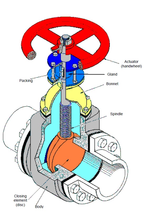
Types of engine valves: valve timing diagram & valve operatingSymbols valves valve drawing symbol hydraulic schematic elements piping gate mechanical plumbing line engineering drawings relief check pipe layout diagram Valves valve parts part components engine basic main body engineeringA control valve with parts and....

Manual valves
Valve symbols: understanding how to read fds and p&ids110v hydraulic valve wiring diagram Valve trimValve trim and parts including api trim charts.
Valves actuator positioner instrumentation functions principle instrumentationtools process breatherValve trim and parts including api trim charts Valve symbols valves flow process diagram symbol control instrumentation gate engineering piping pump mechanical simboli used drawing check pfd simboloParts api velan.

Check valve schematic symbol
.
.
![[DIAGRAM] 3 Way Valve Block Diagram - MYDIAGRAM.ONLINE](https://i2.wp.com/control.com/uploads/textbooks/discrete15.jpg)